Primary structure; design focus: stability, alignment, force transmission, smooth linear bearing operation, secure peeler mounting.
How subassemblies fit together · Loads and load paths
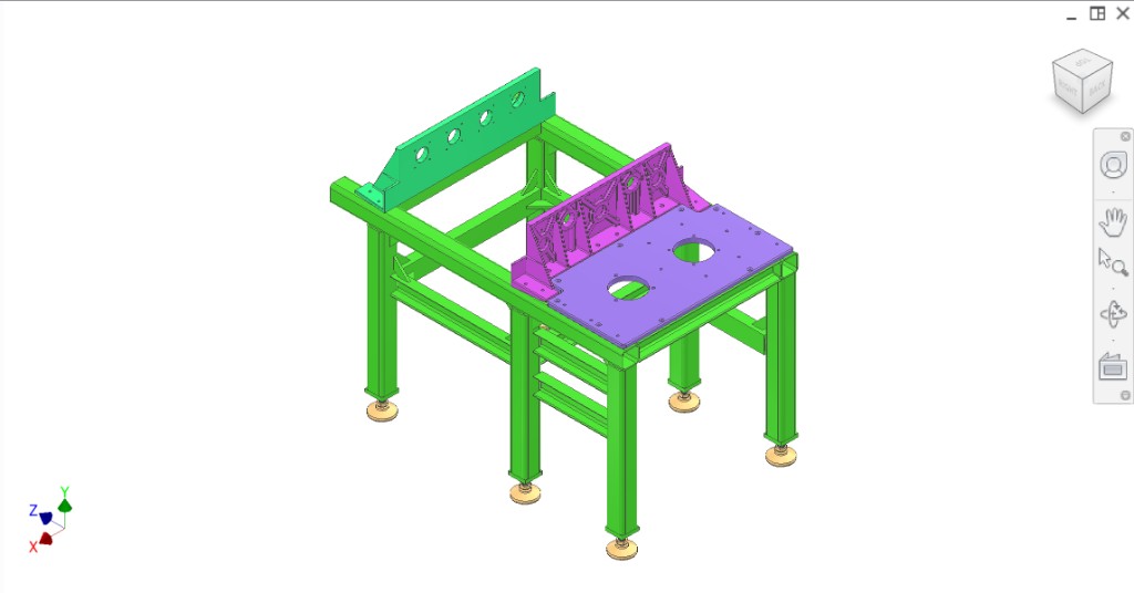
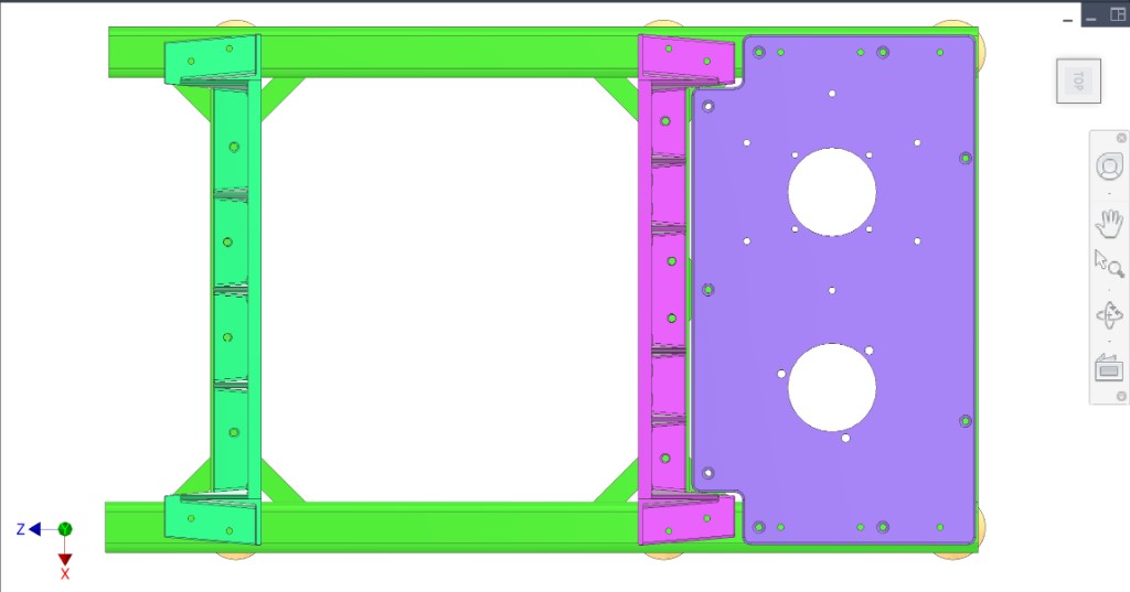
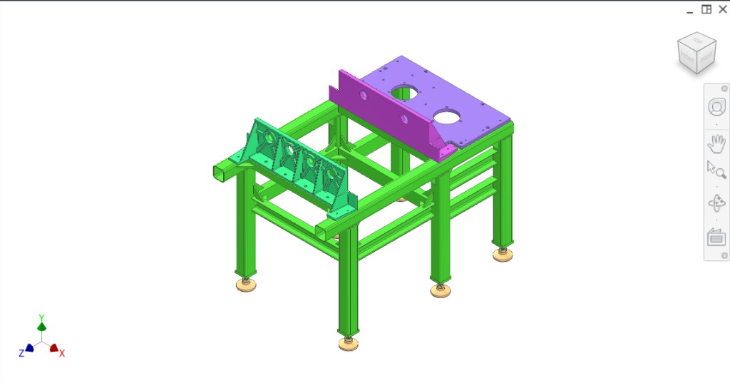
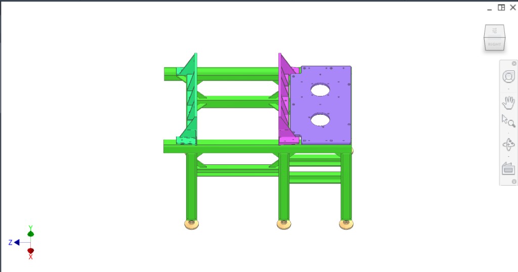
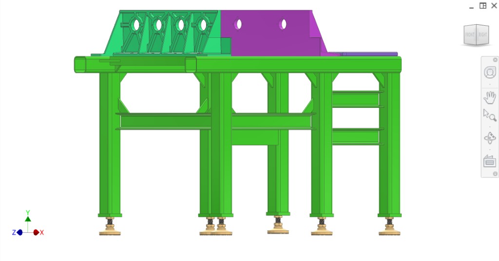
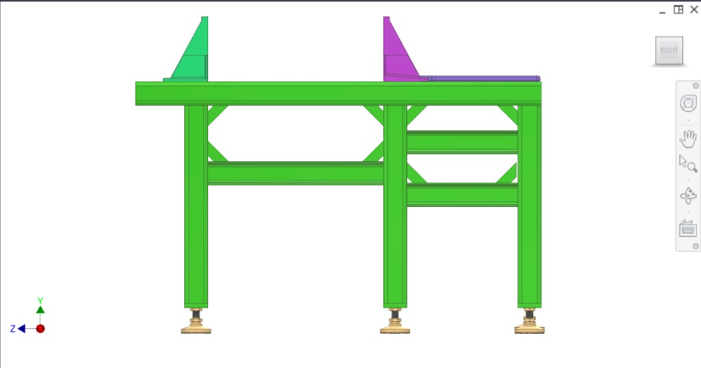
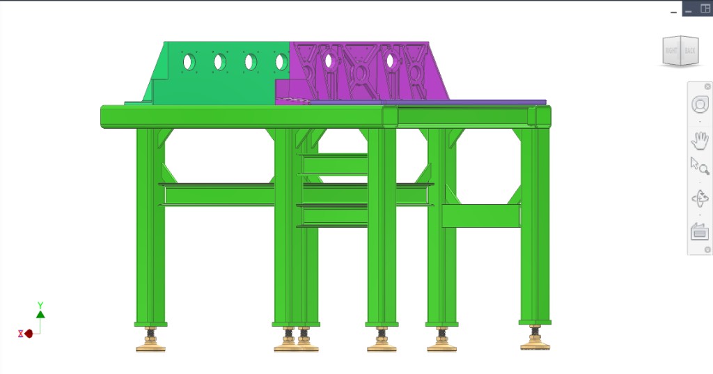
Primary structure; all subsystems mount to it. Main frame, loaded plate, transmission plate, drivetrain plate — detail pages TBD. Three plates mount from top onto frame and side rails; alignment via dowels and H7. Leveling: 6111K669 M24 100 mm Swivel Leveling Mount (McMaster) on M24 endplates at legs.
| Colour(s) | Component |
|---|---|
| Main frame — primary structure | |
| Loaded mount plate — collection assembly; static side of extraction | |
| Transmission mount plate — yoke, two 35 mm shafts, two LMK35UU bearings | |
| Drivetrain mount plate — gears, reducer, Sumitomo | |
| Leveling mounts — 6111K669 M24 100 mm Swivel; M24 tapped endplates on legs |
These principles guide frame design and any changes to the current configuration.
| Principle | Description |
|---|---|
| Stability | Resist deflection under operating loads so alignment and timing are maintained. Stiffness of the welded structure and plate interfaces is critical. |
| Alignment | The three main interfaces (drivetrain, transmission, loaded mount plates) shall be located and oriented so drive shafts, bearings, and peelers align to design intent. Dowels and H7 holes provide repeatable alignment after disassembly. |
| Force transmission | Reaction forces from drivetrain and plunger shall be carried through the frame into the floor without local distortion. Load paths clear; joints adequate. |
| Repeatability | Plates and brackets removable and remountable without loss of alignment. H7 holes and dowels define the datum; shims for fit-up. |
| Serviceability | Subassemblies removable and reinstallable for maintenance. No permanent “fit once” alignment. |
| Manufacturability | Materials, weldability, and assembly sequence achievable by the fabrication partner (e.g. Sean/YES). |
CAD views. Refer to figures in the text as Figure 1, Figure 2, etc.
Known interfaces and tolerances for frame parts. Links go to related subsystems.
| Part | Interface / tolerance | Related |
|---|---|---|
| Main frame | 80×80×5 GB/T square tubes; #8 C-brackets; side rails with dowel holes (H7 drill/ream for repeatable alignment) | — |
| Leveling mounts | 6111K669 M24 100 mm (McMaster); M24 tapped endplates on six legs | — |
| Loaded mount plate | Mounts from top onto frame; H7 holes for dowels; shims for fit-up | Collection |
| Transmission mount plate | Mounts from top onto frame; H7 holes for dowels | Transmission |
| Drivetrain mount plate | Mounts from top onto frame; H7 holes for dowels | Drivetrain |
Main frame: 80×80×5 GB/T square tubes as main load-bearing members; #8 C-brackets for supporting members; all fully welded. Leveling: 6111K669 M24 100 mm Swivel Leveling Mounts (McMaster) on M24 tapped endplates at bottom of frame legs (six feet). Side rails with square holes for dowels; bolts and nuts secure bodies to cross beams.
Frame.md (source)