Part of the Frame section. How operating loads are carried through the frame to the floor.
Primary loads
The frame must carry reaction forces from the drivetrain, transmission, extraction (driven bracket and peelers), and core ejection (plunger drive) without excessive deflection. Alignment between yoke, bearings, and peelers must be maintained for timing and bearing life.
Source
Load type
Path through frame
Drivetrain (motor, reducer, gears)
Reaction to drive torque; weight of motor, reducer, gear train
Drivetrain mount plate → side rails → main frame → leveling mounts → floor
Transmission (yoke, shafts, bearings)
Reaction to linear stroke force; inertia of yoke and driven mass
Transmission mount plate → side rails → main frame → leveling mounts → floor
Extraction (driven bracket, peelers)
Compression force during juicing; reaction from static peelers
Loaded mount plate (collection side) ↔ driven bracket; loaded plate → side rails → main frame → floor
Core ejection (plunger drive)
Reaction to plunger force (compression springs, rod load)
Plunger housings and bracket react into loaded/collection structure; into loaded mount plate and side rails → main frame → floor
Key load cases (to validate)
Current values below are preliminary and intended to help contractors define load cases and acceptance targets. Contractor to validate with final geometry, belt center distance, gear module/profile, and cam/yoke details.
Motor / belt / reducer excitation — WEG W21/W22 IE3 motor (7.5 kW / 10 hp) drives the reducer via SPA belts (ratio currently 1:1; two belts planned). Belt tensioning and motor vibration transmit radial loads and vibration into the drivetrain mount plate and frame.
Reducer output / gear mesh — Target reducer output speed ~70 rpm. Preliminary drivetrain calculations indicate ~1023 N·m torque at the driven gear, with estimated gear mesh forces on the order of ~6.6 kN tangential and ~7.2 kN normal (to be validated).
Cam-yoke reciprocation — Cam bearing offset ~89 mm from shaft axis drives yoke reciprocation. This introduces cyclic forces and moments into the transmission mount plate, the two drive shafts, and their supports.
Peak compression event — Worst-case operating condition assumes maximum drivetrain capability drives the extraction/compression event; frame and mount plates should withstand this with an appropriate factor of safety and without losing alignment.
Moments at linear bearings and mount plates
The transmission uses two shafts guided by two LMK35UU (35 mm) linear bearings. The bearings are located above the mount plate, so off-axis forces and any asymmetry between left/right sides generate moments into the transmission mount plate and the frame.
Asymmetric / jam case — If one side binds or sees higher friction than the other, the shafts can twist and impose additional moment loads on the linear bearings and plate.
Overturning moments — Vertical offset between bearing reaction line and the mount plate creates an overturning moment that tends to rotate the mount plate about a horizontal axis. This is expected to be significant on the collection side during compression.
Load transfer — These moments must be carried through the mount plate into the dowel/shear pins and bolted clamping into the side rails, then into the welded frame and down into the leveling mounts and floor.
Load path principles
Clear paths — No single member or joint should see disproportionate load; loads should spread through the welded structure and into the three plates as intended.
Minimise deflection — Stiffness of the main frame and plate interfaces is critical so that yoke travel, peeler mesh, and plunger alignment stay within design intent.
Reaction into floor — All operating loads must be carried down through the legs into the leveling mounts (M24 endplates) and the floor; no floating or cantilevered reaction paths.
Joints — Bolted interfaces (plates to frame, brackets to plates) must be adequate for shear and tension; dowels carry locating and shear where specified.
Notes for RFP
Contractors are asked to verify and document load cases and load paths for the as-built configuration, and to propose practical acceptance targets for stiffness and alignment (including asymmetric/jam cases for the transmission shafts). Where appropriate, contractors should recommend whether simplified calculations are sufficient or whether FEA is warranted for the frame weldment and/or critical mount plates.
Questions for contractor
Derive validated load cases (motor/belt radial loads from tensioning, gear mesh forces, cam-yoke reciprocation forces, peak compression), and provide force/moment estimates at each mount plate interface.
Validate or correct the preliminary drivetrain figures (~1023 N·m torque at driven gear; ~6.6 kN tangential and ~7.2 kN normal gear forces) and document assumptions.
Quantify moments and bearing loads for the LMK35UU-guided shafts, including an asymmetric/jam case, and recommend mount plate stiffness and joint design.
Recommend whether FEA is required (frame weldment, drivetrain plate around tapered roller bearing, transmission plate around linear bearings) and provide boundary conditions and acceptance metrics.
Propose acceptance targets for allowable deflection/misalignment that preserve peeler alignment and bearing life, and recommend inspection checks to verify them.
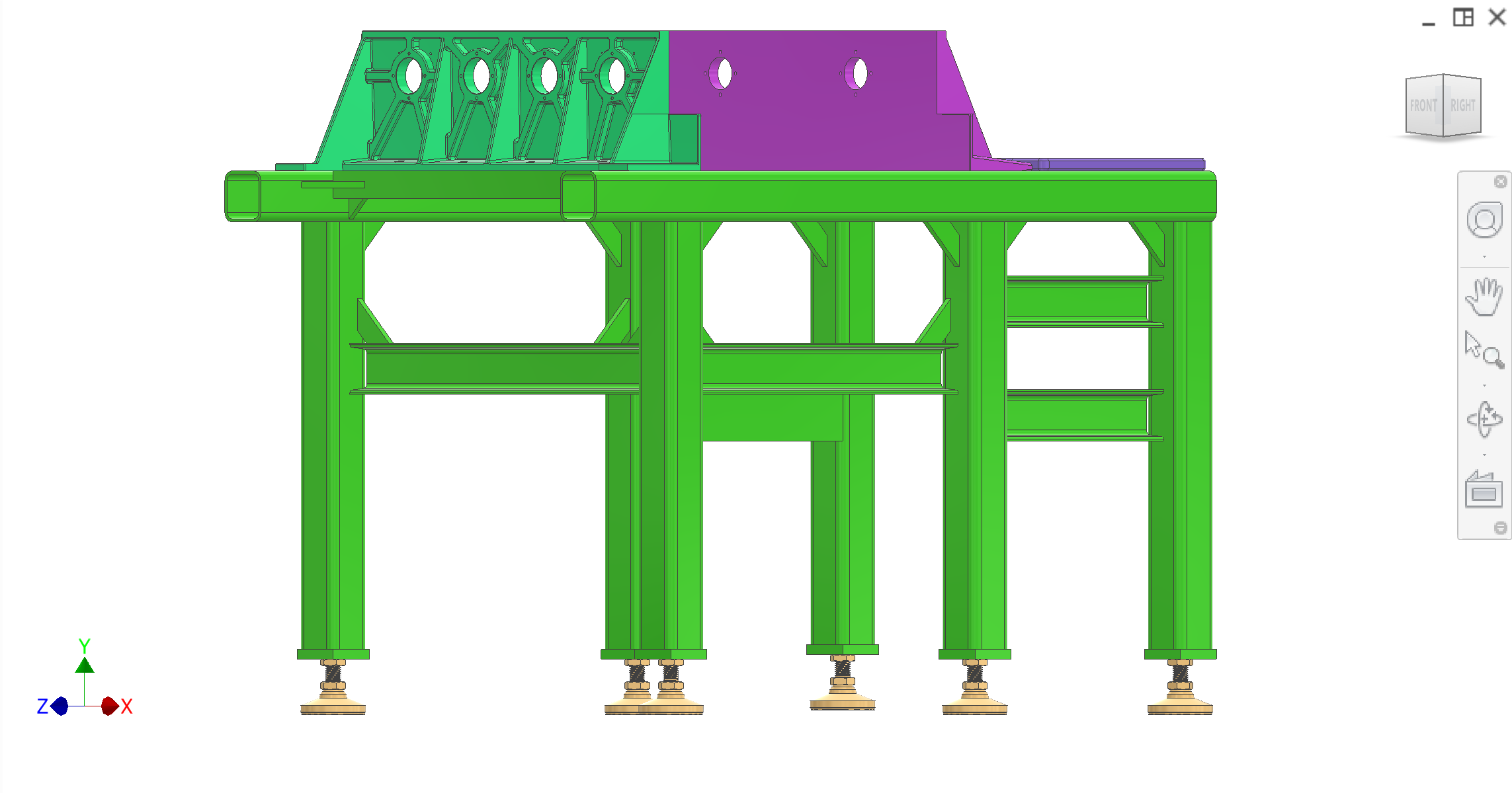
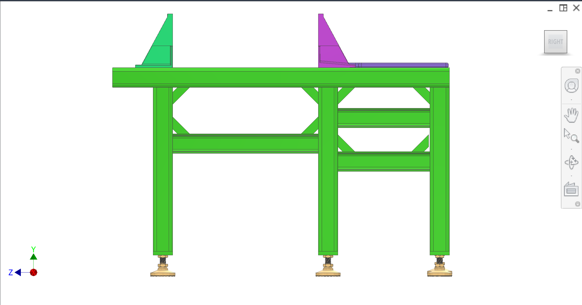
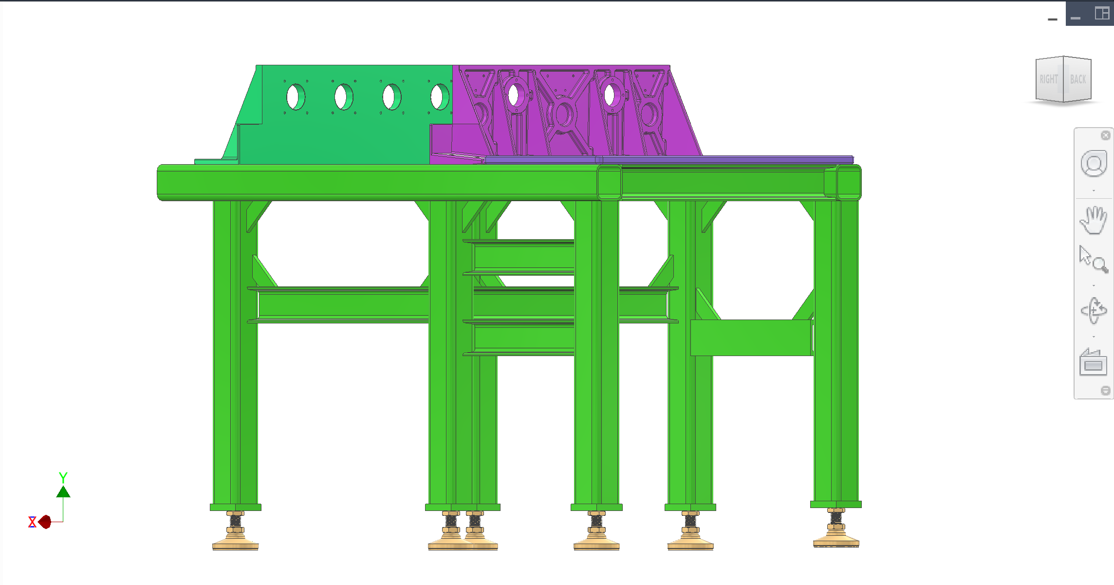
Figures
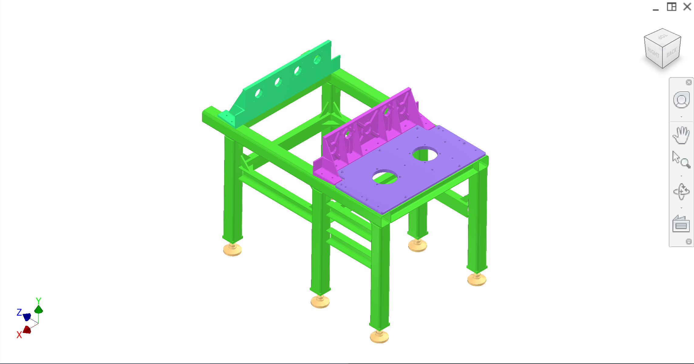
CAD views. Refer to figures in the text as Figure 1, Figure 2, etc.
Figure 1. Isometric — main frame, three interface plates, leveling mounts.