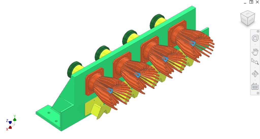
Static peelers (), static deflectors , juice collectors (Y-tubes), filter tube, plug cutter, collection mount plate. Mounts on the frame’s loaded mount plate.
Reminder: Add the supplier link/spec for the 38 mm OD ribbed hose connector used to couple the collector outlet to rubber hose. (Example source: Taobao item 1030645801360.)
Peel deflectors (WIP): The static deflector (this subsystem) and the chute deflector (extraction/synchronisation) are both work in progress. Ensure they are easily manufacturable, do not collide during motion, and are rigid and clean.
Colour key & components
CAD colours for this section. Static peelers, deflectors, juice collectors, filter tube, plug cutter — detail pages TBD.
Colour(s)
Component
Collection mount plate — mounts to frame loaded plate; carries static peelers, deflectors, collectors, filter tube, plug cutter.
Static peelers — interlace with driven peelers to mash fruit
Static deflectors — redirect peel to front of bin; flat plate; mounted to loaded plate
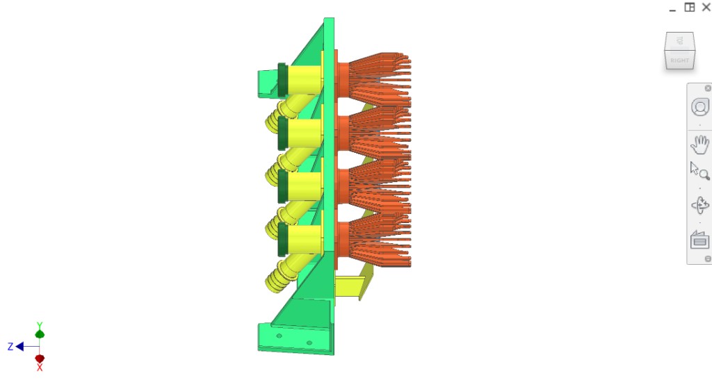
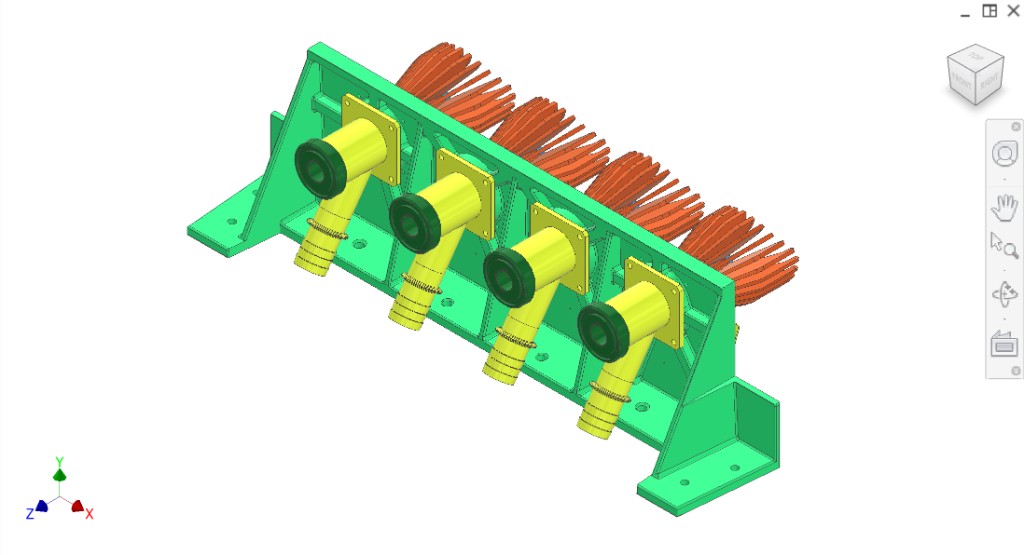
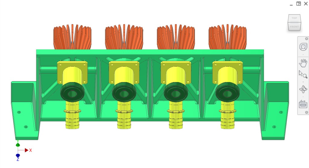
Juice collectors (Y-tubes) — collect juice from filter slots; 34 mm quick-connector outlet and ribbed hose connection.
Filter tube — juice flows through slots into collector
Plug cutter — cuts centre plug from oranges
Figures
CAD views (with static deflectors). Refer to figures in the text as Figure 1, Figure 2, etc.
What this subsystem does — Provide the static extraction half (static peelers) and collect juice through the filter tube into collector Y-tubes, then route juice to third-party tanks/pumps. Also integrates the plug cutter and supports core ejection through the filter tube.
Juice collector tube concept — Current concept uses standard stainless tube sizes for China availability: main collector body ~57 mm OD (chosen as a standard size; not strictly required) and a juice outlet tube sized to accept quick-connect hardware (current concept: ~38 mm OD outlet to connect to rubber hose via a ribbed connector).
Filter tube — Structurally similar to the commercial machine but longer; planned as hardened steel with laser-cut vertical slots (~0.7 mm slot width concept) and a scraper/plunger interface that clears pulp each cycle.
Collection mount plate — Same overall idea as the transmission mount plate: stiff, alignment-critical, cleanable. Inner surface finish target is high (Ra ~0.8 μm concept) and must support peeler and collector alignment.
Known issues & risks
Seal leakage at plunger/filter tube — Known issue: juice leaks past plunger-to-filter-tube interface; expected to worsen at higher industrial pressures. O-ring or alternate seal strategy may be needed.
Wear — Prior configuration had 304 scraper against 304 filter tube, roughening the tube ID. Current intent is hardened steel for improved wear; contractor to validate.
Filter tube alignment sensitivity — Filter tube is welded to a cap and then assembled (screwed) into position; stack-up can shift alignment and worsen plunger sealing and wear.
Collision risk — Static vs driven peelers must not collide; static deflectors must not deform and contact chutes or peelers over time under vibration and juice exposure.
DFM & manufacturing (China)
Tube fabrication — Prefer standard tube sizes and welded assemblies using China-available sanitary/quick-connect fittings.
Hardened tube processing — Contractor to propose how to manufacture, harden, and finish (ID grind) the filter tube while keeping slot geometry accurate and cleanable.
Hygiene — Internal surfaces that contact juice should be cleanable, smooth, and avoid crevices (finish targets to be confirmed with contractor and sanitary rules).
CIP / cleaning concept
T-valve mode switch — Concept: use a T-valve to switch between sending juice to tanks vs feeding CIP fluid into the collector outlet.
Reverse-flow cleaning — CIP fluid enters via the outlet tube, flows into the collector/juice chamber, then up through the filter tube and out through the centre of the plug cutter to flush slots and clean internals.
Questions for contractor
Propose a robust sealing strategy for plunger-to-filter-tube to reduce juice leakage under higher pressures (O-ring, lip seal, tighter finish/tolerance, alternate geometry).
Recommend material + heat treat + finishing for filter tubes and plug cutters to manage wear from scraper action and maintain hygiene.
Propose an assembly and alignment method that keeps filter tube and plunger alignment stable (especially given “welded cap + screw-in” stack-up).
Validate the CIP reverse-flow concept (T-valve switching, flow path, cleaning effectiveness) and propose any required check valves/filters.
Recommend manufacturing strategy for collector tubing and quick-connect interfaces using common China sanitary components.
Figures to add (clarify to contractors)
Juice path schematic — slot flow → collector body → outlet → third-party; plus reverse-flow CIP path.
Seal detail — plunger-to-filter-tube interface (current vs proposed O-ring).
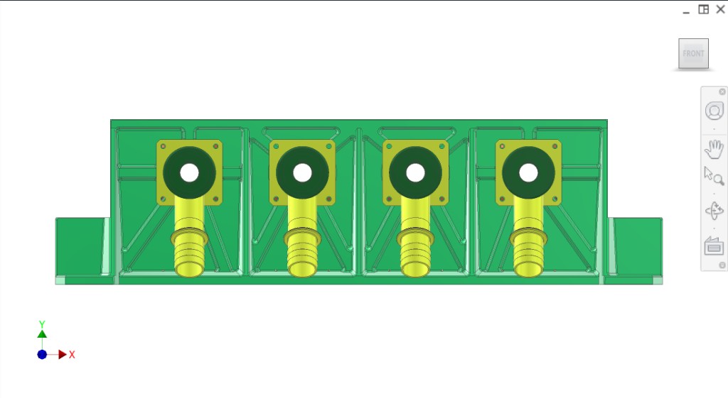
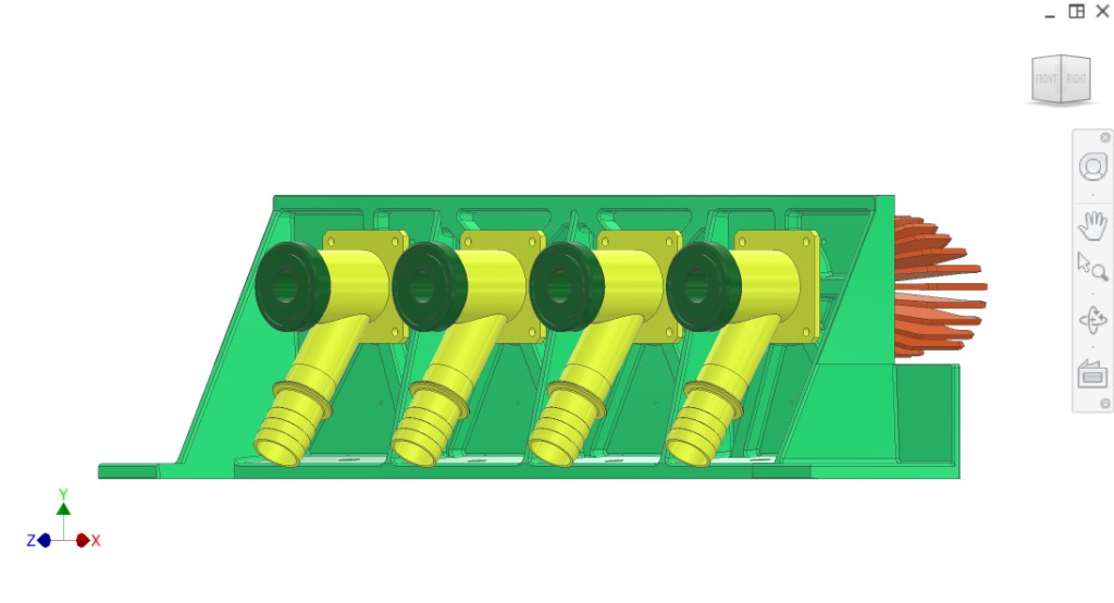
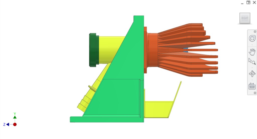
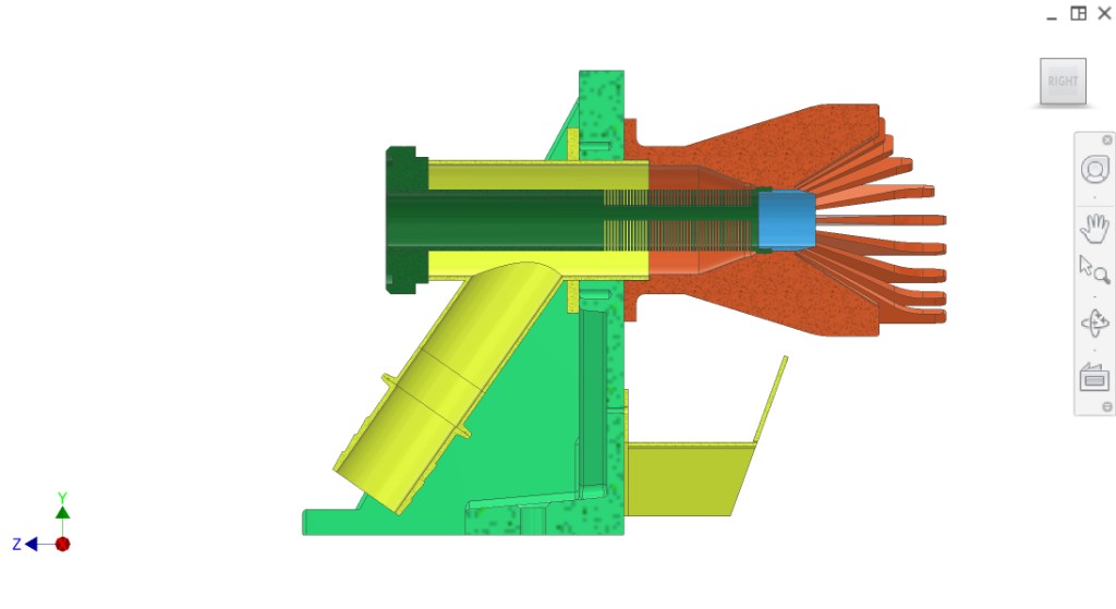
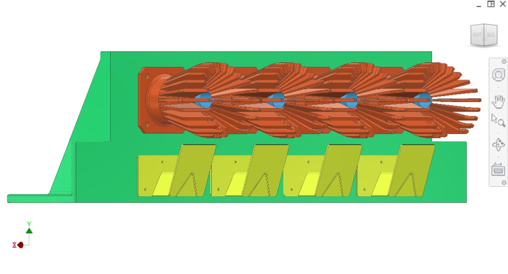
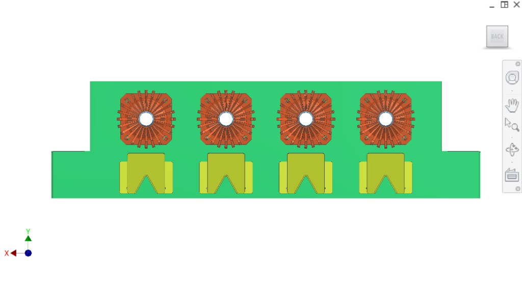
Driven and static peelers () mesh; oranges fall between them; fingers interlace → fruit mashed, peel squeezed into extraction chamber and outflow chute. Static deflectors redirect peel from the base of the peeler to the front of the bin; mounted to the static loaded plate; flat plate design (see Figure 1, Figure 5, Figure 10).
Plug cutter (#4DB7F5) cuts a cylindrical plug from the centre of oranges during juicing.
Juice flows out of oranges through slots in the filter tube (#287F3F) into the yellow collector (#FFFF50), then out via the Y-branched tube to a ribbed connection for standard rubber pipes.
Extraction cycle and disposal
After the pressing stroke (juice to Y-section): the core ejection system pushes a plunger through the filter, pushes the core back out of the plug cutter, and the core falls into the core chute of the disposal system. Meanwhile, peels fall to the sides of the peelers, avoid the core chutes, and separate into two channels; the disposal system (two augers) takes peels and cores away separately.